Magnetic field control system for the REX-ISOLDE isotope accelerator at CERN
As a technical leader of a project, I was responsible for the design and development of a magnetic field control system. The main purpose of the activity was to achieve optimal field precision and stability for the magnets, using existing controls infrastructure in the CERN laboratory responsible for the research of a radioactive isotopes (ISOLDE). This post describes the field, the control and the supervision layers of the control system, as well as the C++ Front End Software Architecture (FESA) framework used to implement the magnetic field control algorithm.
Introduction to the ISOLDE facility
The ISOLDE facility is one of the world’s leading laboratories for the production and investigation of a radioactive nuclei. It is located on the border between Switzerland and France and it is part of CERN’s accelerator complex. It has been in operation since 1967. Presently it is receiving a high energy proton beam from the Proton Synchrotron Booster (PSB), which in reaction with thick targets produces radioactive isotopes. The success of the facility is due to the continuous development of new radioactive ion beams and improvement of the experimental setups. Currently, the ISOLDE is able to produce 1000 isotopes of 70 chemical elements. The energy of the investigated radionuclides ranges from ![]() eV to 3 MeV thanks to the post-accelerator REX-ISOLDE.
eV to 3 MeV thanks to the post-accelerator REX-ISOLDE.

The facility provides two stations where the targets can be mounted, namely the general-purpose separator (GPS) and the high-resolution separator (HRS). Both perform accurate discrimination by mass, which eventually gives optimal selection of a particular isotope. Depending on the experimental constraints, it is possible to choose either the GPS or the HRS system. In order to post accelerate the radioactive nuclei, first the isotopes are trapped in a Penning trap (REXTRAP) to lose energy through collisions with the buffer gas. Afterwards, the ions are sent in bunches to the electron beam ion source (REXEBIS), where the bombarding electrons collide with electrons bound to ions, further ionising these ions. The ionisation states depend on the time the ions are being ionised. Longer times result in higher charged states. Despite the high vacuum, at the exit of REXEBIS some unwanted components — such as residual gases — can still be found in the beam. Furthermore, a variety of charge states are present. For that reason, a dedicated mass separator for REX is located after the electron beam ion source. It consists of an electrostatic 90° cylinder deflector and 90° magnetic bender arranged in a vertical S-shape. After separation, the resulting nuclei are injected into a LINAC, where they are accelerated. At the end of the acceleration beam line, the main bending magnet is installed. Its main purpose is to switch the nuclei into one of the two beam lines: the Miniball at 65° and the second one at 20° which is reserved for dedicated experimental setups.
Common software interface for the power converters
To supply the beam to the ISOLDE experiments without any interruptions, stable electric and magnetic fields have to be assured in many elements of the beam line in the facility. To achieve this, high-voltage and high-power power converters are used. As the facility is equipped with more than 500 power converters, a common control solution had to be developed. During the design phase it was established that information about the desired mode of operation, as well as the voltage/current reference would be defined from the control room. As a feedback, the devices should share information about their health check status, actual device mode and real voltage/current values. It was decided, that a solution based on Programmable Logic Controllers (PLCs) would be the most efficient and cost effective. For this reason, the ISOLDE facility was split into divisions based on the main functions of its elements (GPS, HRS, REX, etc.). Dedicated PLC setups were prepared. Depending on the number of devices handled by one controller, the SIEMENS SIMATIC S7-300 or S7-400 CPUs series were selected accompanied by I/O modules. The software deployed on those PLCs did not have any logic implemented concerning regulation or mode handling. The voltage and current loops were handled by the converters.
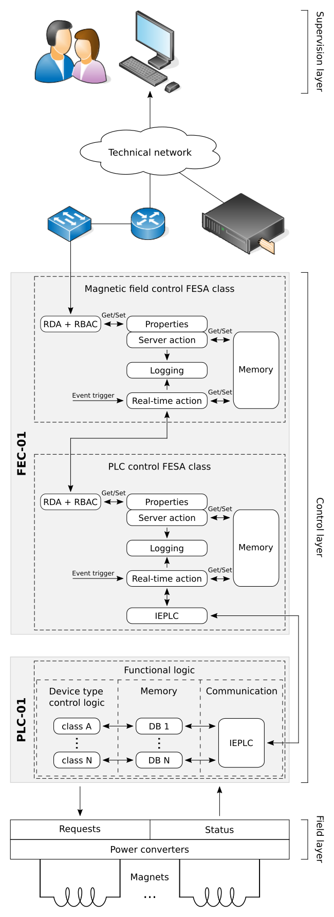
The PLCs are used as servers following a client-server model. They provide a service which is an interface to the power converters. Their only duty is to properly and safely set the current/voltage and mode, depending on the requests from the higher level applications. Each program running on the programmable logic controller has a specific structure. Only owning this knowledge gives the ability to read the desired information from the proper places in the memory. In order to provide the higher level programs with a unified way of accessing the PLCs’ data, a common software interface was defined. A server application implementing it was developed on top of each PLC. It was built using the CERN real-time Front End Software Architecture (FESA) and is running on a Front End Computer (FEC). The communication from or to the controller is assured by Ethernet Interconnection for Programmable Logic Controllers (IEPLC). It is a framework developed at CERN which defines communication interfaces in a hardware independent manner.

General architecture of the magnetic field control system in the ISOLDE facility at CERN.
The Front End Software Architecture (FESA)
The FESA is a complete environment for equipment specialists to design, develop, generate, test and deploy real-time control software written in C++. It has been integrated in the Eclipse IDE as a plugin. Each FESA class is considered to be a representation of a device type and allows management of a different instances of this certain type. It is event driven and uses thread priorities for scheduling. The FESA engine was split into two parts. The first one implements on demand request handling, providing the equipment interface and middleware access. The second one implements real-time hardware control, which can be triggered by different types of event sources: timer, accelerator timing, custom events defined by the user, on demand events (triggers real-time action from server side) and on subscription event. As a rule, both services run on the same hardware platform, but it is possible to run them separately as two different processes.
Other software — also other FESA applications — have different possibilities to exchange the data with a FESA classes. The controls middleware (CMW) brings a common software communication infrastructure for the CERN accelerator controls. The CMW Remote Device Access (RDA) is used as a transmission interface to a front end software architecture classes. This allows FESA equipment to be represented as a collection of a different FESA classes, which depend on each other. This approach was used to create a magnetic field regulation class deployed in the ISOLDE facility.
Magnetic field regulation FESA class
To achieve the optimal magnetic field precision, stability and to simplify the operation handling of the main bending and switching dipoles in the REX-ISOLDE, the magnetic field regulation class was developed. Its main purpose is to run the magnetic field control algorithm. Depending on the calculation outcome, it sends current setting requests to the power converters through the FESA class built on top of each PLC. This field regulation class is based on the newest version of the FESA3 framework and the RDA3 communication library. It uses a remote device access API to subscribe, obtain and modify the collections of data — called properties — from the PLC interface FESA class. The field regulation software monitors the following properties: status, setting and acquisition. From the first one, the mode, the control type and the health check of the device can be read. The second one gives the ability to read/set the current and operational mode of the power converter. The last one provides information about the actual current and magnetic field measurements. Having this information and current to field coefficients for the given magnet, the control algorithm is able to calculate the error between the actual and requested value of the magnetic field. Afterwards, it sends the new current request with the corrected error to the PLC interface FESA class, which eventually passes the data using IEPLC to the programmable logic controller that handles the power converter.
The field regulation algorithm uses five machine states but only four logical phases are associated to it. The first two states (OFF and OFF_ERROR) use the same step to signal that the field regulation is disabled or an error occurred. Only SETTING, ADJUSTMENT and STABILIZATION states are used for the control of the magnetic field. First, the algorithm sets the requested magnetic field value and waits for the stable measurements. If an error between request and average field value from measurements is higher that the deadband, it recalculates the current and sets it again. When the error value is in the accepted range, the field is stabilized. If the error goes again above the limits, the algorithm tries to compensate and it readjusts the field once more.
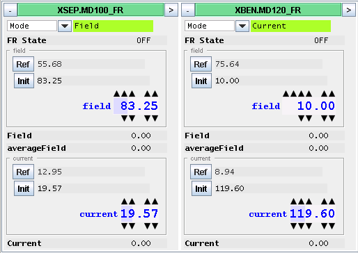
The magnetic field regulation C++ class provides an interface so other applications can be built on top of it. It has already been used for the development of the software for the mass separator, as well as for the Injector Control Architecture (InCA) working sets, which provide the supervision layer not only for the ISOLDE facility, but also for the LHC injection chain.
Injector Control Architecture (InCA)
The InCA is a software system which homogenizes the control systems across the CERN accelerator complex. It provides generic applications, as well as an API with high level functionality for specific Graphical User Interface (GUI) development. In addition, in order to protect FECs hosting real-time software, it can act as a proxy server by providing all information from the applications to which it is subscribed to, thus reducing the perturbation caused by requests from different applications.
Injector Control Architecture is based on a three level design, which offers very good scalability. The first layer of the system consists of equipment — mostly dedicated computers — responsible for real-time control of the hardware. The middle tier provides high level services. One of its parts is the LHC Software Architecture (LSA) which is responsible for settings management. Acquisition Core (AcqCore) provides monitoring, processing and redistribution of the hardware values. The last application running on this level is the Configuration Service, which brings efficient retrieval of configuration data. The client applications are located on top of the architecture. Their main task is to access the middle layer services. This software is built with generic elements provided by InCA, which enables the surveillance of all the equipment in a unified way.

Summary
The described regulation system is successfully managing the magnetic filed in the ISOLDE facility at CERN. Dividing the control layer of the system to two C++ FESA classes and using programmable logic controllers as interfaces to power converters was a good design decision. The implemented solution proved to be very flexible and robust. It standardizes the interfaces of the power converters and moves the regulation to a higher layer. This approach makes it easy to extend the control system by building regulation classes on top of each other.
On the other hand, it should be borne in mind, that because the control layer of the system consists of more than one program, this architecture is not recommended for controls with real-time constraints, as several tiers of the application introduce a delay caused by communication data exchange.


